Balancing Valves for Chillers and FCUs: Selection and Installation

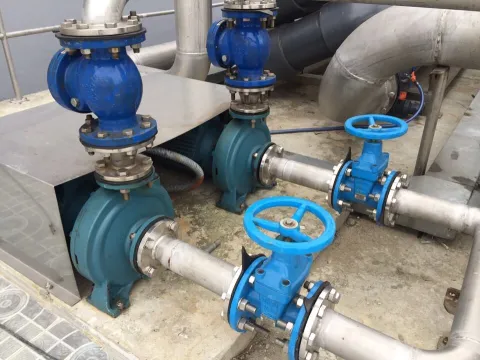
Select a balancing valve for a chiller and FCU system by the design flow and the pressure drop you want on each branch, not by pipe diameter. Tecofi offers threaded valves for small branches (DN15 to DN50) and flanged valves for risers, larger branches and distribution headers, and both have pressure test points so you can measure the differential pressure and then set the opening. Install the valves on the return branches, set them to the design flow and lock the memory position.
This article covers selection and installation. For the basics (static and dynamic types), see What Is a Balancing Valve? Design, Types and Setting.
Why a chilled-water system needs balancing
According to Tecofi (France), hydraulic balancing brings the required flow to every point of the system. In one building some rooms may struggle to reach the required temperature while others are overheated, because poor flow distribution stops the control loops from doing their job. Tecofi also states that a well-balanced hydraulic network can save 10 to 20% of energy, or more in some cases. That is the manufacturer’s figure; actual savings depend on each project.
Balancing also supports troubleshooting: with balancing valves and test points you can measure flow or differential pressure at any point of the network and trace a problem to the branch causing it. When the system is extended, the extension must also be balanced because the original flow increases.
Where to install the valves in a chiller and FCU system
Tecofi’s example is a system with three risers, where the upstream risers take a larger share of the flow and the last riser is under-supplied. The fix is to fit balancing valves on the return branches so that the flow is shared evenly between risers; each valve ends up at a different opening (in the manufacturer’s example the last riser’s valve is almost fully open and the first riser’s valve is set lower). A larger flanged valve at the distribution header absorbs part of the network’s pressure drop, which lets the smaller balancing valves work in a better adjustment range.
The same principle applies to a chilled-water loop: valves on the return of each riser, FCU group or AHU, and one at the distribution header. The exact positions depend on the system diagram and should be confirmed by the designer.
Choosing among the Tecofi balancing valves
| Model | Type | Materials | Manufacturer data | Used for |
|---|---|---|---|---|
| RC2152 | BSP female thread | Bronze body CC 491 K, DZR brass disc | DN15 to DN50; 25 bar; -10°C to +120°C; DZR brass pressure test points | Small branches, FCU groups |
| RC4240 | Flanged, variable orifice | Ductile iron GGG40 body and bonnet, ductile iron disc with EPDM | PN16 or PN25 depending on the order code; -10°C to +120°C; 2 steel pressure test points | Risers, larger branches, distribution header |
| RC4241 / RC4251 | Flanged, fixed orifice | Ductile iron GGG40 body and bonnet, disc with EPDM | PN16 (RC4241) or PN25 (RC4251); -10°C to +120°C; 2 steel pressure test points | Larger branches that need a fixed orifice |
The flanged range has an oblique seat, an opening indicator with travel limiter, and a memory position with a locking screw in the head; the pressure test point can also be used for draining and filling. See the overview on the Tecofi balancing valve page and the balancing valve category.
Sizing
Valve size is calculated from the design flow and the pressure drop wanted on the branch, not from the pipe diameter. Send the design flow and pipe DN of each branch and CAD engineers will size the valve.
Installation and setting
- Measure the differential pressure across the valve at its two test points and compare it with the valve characteristic supplied by the manufacturer to convert it to flow.
- Adjust the opening to the design flow, then lock the memory position with the locking screw to keep the balanced setting.
- Tecofi has its own measuring instrument, the Tec’Control (static pressure, differential pressure and flow, with Bluetooth connection to an Android/iOS app), for balancing heating and air-conditioning systems.
- HVAC systems can also be controlled with a BMS / HVAC Control solution, while balancing valves keep each branch at its design flow.
What to send CAD for a quotation
- System type (chilled water, FCU, AHU, hot water) and valve position (supply or return branch, distribution header).
- Design flow of each branch (l/s or m3/h) and pipe DN.
- The pressure drop wanted across the valve, or the system working pressure.
- Pressure class (PN16 or PN25) and water temperature.
- Connection: BSP thread or flange.
- Quantity of each size and whether you need a measuring instrument.
Send the model or specification and CAD will quote within 24 working hours.
Frequently asked questions
What does a balancing valve do in an HVAC system?
It gives each branch its design flow, so branches near the pump are not over-supplied while distant ones are starved. Room temperature is more even and the pump works at its intended point.
How do I size a balancing valve?
By the flow and the pressure drop wanted on the branch, not by pipe diameter. Send the design flow and pipe DN and CAD engineers will size the valve.
Can the RC2152 be used for chilled water?
The manufacturer rates the RC2152 for -10°C to +120°C at 25 bar, which covers normal chilled and hot water systems. Send your actual temperature and pressure so we can confirm.
Do I need an instrument to set a balancing valve?
Yes. The valve has pressure test points for measuring differential pressure, from which flow is derived and the opening is set. Tecofi has its own instrument for this.