What Is a Gas Train? Components, Diagram and Safety Standards for Industrial Burners
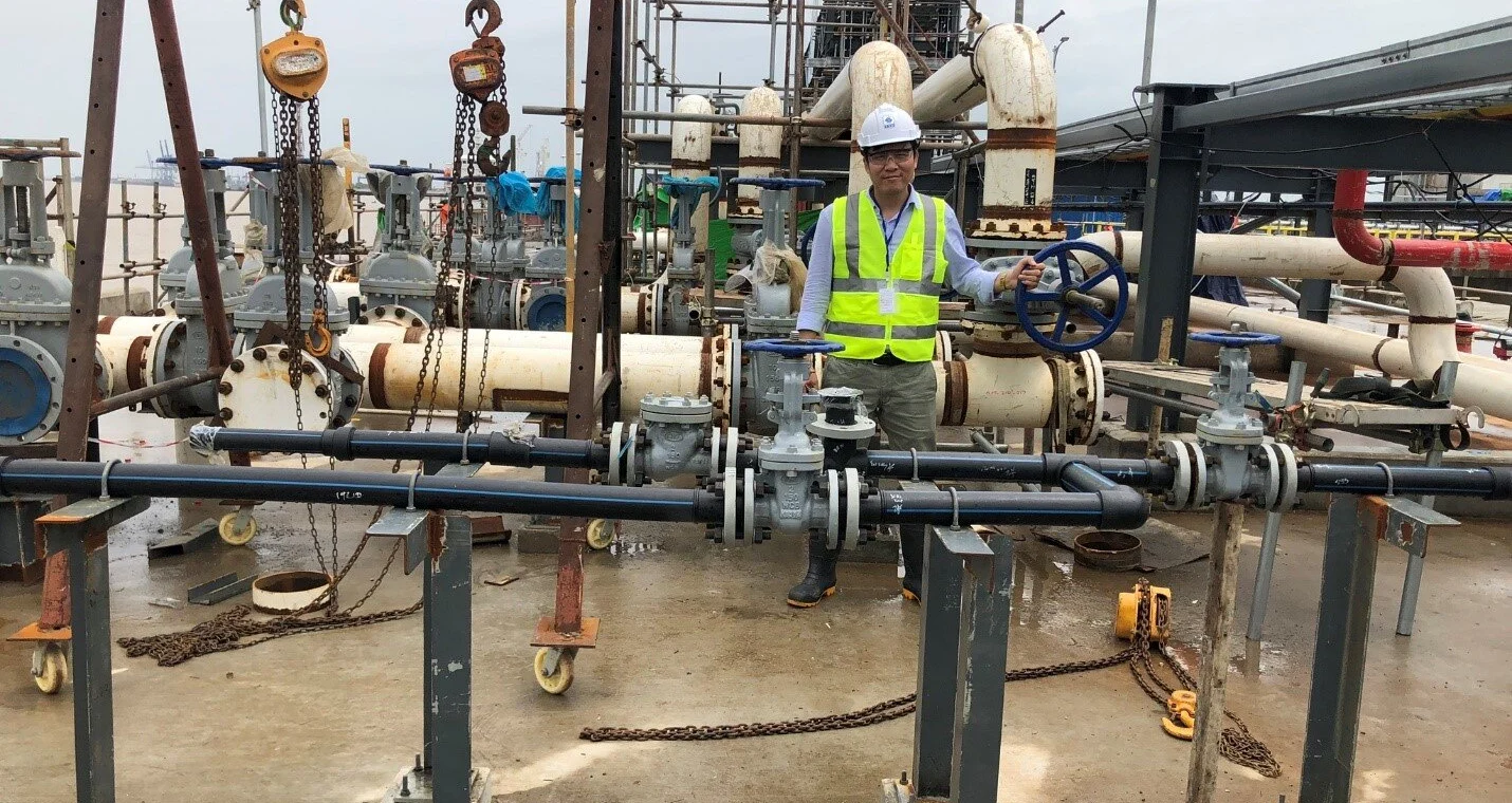
A gas train (also called a gas ramp or burner gas valve train) is the assembly of pipework, valves and instruments between the gas supply and an industrial burner. It filters the gas, reduces and stabilises its pressure, monitors that pressure, shuts the gas off safely when something goes wrong and delivers the right flow to the burner. Understanding the gas train is the first step to specifying a complete set of equipment and to running the combustion system of a furnace, oven or boiler safely.
Key points
- The gas train is the “gas line” of a combustion system; the “control” side is the burner controller and the flame sensor.
- A complete gas train usually includes a manual shut-off valve, a filter, a pressure regulator, low/high gas pressure switches, safety shut-off valves and a flow control valve.
- Standards commonly used as the design basis: NFPA 86 (ovens and furnaces), NFPA 85 (boilers), EN 746-2 (now EN ISO 13577-2) and EN 676 (gas burners).
- The exact configuration depends on the gas type, supply pressure, burner capacity and the standard that applies to each plant.
Where the gas train sits in a combustion system
An industrial gas combustion system has four groups: the burner, the combustion air line, the gas line (the gas train) and the control and safety group, made up of the burner controller and the flame sensor. The gas train runs from the plant’s gas supply point (a regulating station or the main pipe) to the burner’s gas inlet. On a furnace with several burners, one gas train can serve the whole zone, with a manual shut-off valve added for each burner. All of this equipment belongs to CAD’s Process Thermal group.
Main components of a gas train
The order below is a typical configuration, from the gas supply to the burner. A real design may add or omit equipment depending on capacity, gas type and the applicable standard.
| Device | Role | Notes |
|---|---|---|
| Manual shut-off valve | Isolates the gas for maintenance or fault handling | Fitted at the start of the line |
| Gas filter | Catches dust and debris so valves and the regulator do not jam | Watch the pressure drop across the filter to know when to clean or replace it |
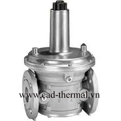
| Gas pressure regulator | Reduces the supply pressure to the burner’s working pressure and holds it steady as the load changes | Select by inlet pressure, outlet pressure and flow |
| Low / high pressure switches | Tell the controller to stop the burner when gas pressure falls below or rises above the set point | Test periodically as part of maintenance |
| Safety shut-off valves (usually two in series) | Close quickly on a stop command or a fault; normally closed, open only when the controller allows | Solenoid valves or valves with an actuator |
| Vent valve, depending on configuration | Opens when both shut-off valves are closed to lead any leaked gas to a safe place | Used in the “double block and vent” arrangement |
| Valve proving | Checks the tightness of the shut-off valves before or after each burner cycle | Whether it is mandatory depends on capacity and the standard |
| Flow control valve | Sets burner output and keeps the air-gas ratio | Butterfly valve with a servo or an air-gas ratio mechanism |
| Individual manual valve for each burner, pilot line | Isolates each burner; supplies the pilot burner separately | Found on multi-burner furnaces |
Pressure regulators and reducing valves
The regulator keeps the outlet pressure steady so the flame burns evenly. CAD’s range includes the Honeywell HON 240 gas pressure regulator (per its product page: inlet pressure up to 10.3 bar, outlet pressure 0.01 – 0.21 bar), the Honeywell HON 200 pilot-operated regulator for industrial regulating stations (inlet pressure up to 100 bar) and the Kromschröder VGBF gas pressure regulator (maximum inlet pressure 500 mbar, 1 bar or 4 bar depending on the version). See the full gas pressure regulators group.
Safety shut-off valves
The safety shut-off valve is the last barrier between the gas line and the combustion chamber: normally closed, it opens only when the burner controller allows it and closes at once on power loss or a fault. The range includes the ASCO 8214 gas shutoff solenoid valve (closing time under 1 second, 1/8″ NPT test ports before and after the valve), the Honeywell V5055 safety shutoff valve and the Kromschröder VAD / VAG series, which covers pressure regulators with an integrated solenoid valve (VAD) and air-gas ratio control valves (VAG). See the gas shut-off solenoid valves group.
Schematic of a gas train
The sequence below only illustrates the order of the equipment; it does not replace the project’s P&ID.
Gas supply → manual valve → filter → pressure regulator → low/high pressure switches → safety shut-off valve 1 → (vent valve) → safety shut-off valve 2 → flow control valve → burner manual valve → burner
How the gas train works while the burner runs
- The burner controller checks the start permissives: gas pressure in range, enough combustion air, interlocks satisfied.
- The combustion chamber is purged with air to clear any leftover mixture.
- The pilot valve opens and the spark fires; the flame sensor confirms the pilot flame.
- The main safety shut-off valves open; the sensor confirms the main flame.
- The flow control valve brings the output to the set value. If the flame is lost or gas pressure leaves its limits, the controller closes the shut-off valves.
Common safety standards
- NFPA 86 – Standard for Ovens and Furnaces applies to ovens, dryers and heating equipment. Two shut-off valve arrangements are commonly described: two normally closed valves in series (double block), or two valves with a normally open vent valve between them (double block and vent).
- NFPA 85 – Boiler and Combustion Systems Hazards Code applies to boilers with a fuel input of 3.7 MWt (12.5 million Btu/h) or more.
- EN 746-2:2010 (Industrial thermoprocessing equipment – Safety requirements for combustion and fuel handling systems) has been replaced by EN ISO 13577-2 (new edition published in 2023). Under EN 746-2:2010, the gas line to each burner or group of burners passes through two class A automatic shut-off valves to EN 161 in series, and shut-off valves controlling more than 1,200 kW need a valve proving system to EN 1643 or an equivalent level of safety.
- EN 676 covers gas burners with forced draught fans; EN 88 and EN 334 apply to pressure regulators; EN 161 to automatic shut-off valves; EN 1854 to pressure switches. The Kromschröder VAD / VAG and VGBF product pages in CAD’s range list these equipment standards.
Which standard applies also depends on the type of equipment, the place of installation and the requirements of the authority or insurer. This article is only a summary; read the current edition of the standard when you design.
How to choose a gas train for a burner
- Gas type and supply pressure: natural gas, LPG or biogas; the inlet pressure at the tie-in point and how much it fluctuates.
- Burner capacity and turndown: this sets the DN size of the regulator, shut-off valves and flow valve. Too small and the pressure drops when the burner runs at full load; too large and control is poor at low load.
- Applicable standard: a furnace to NFPA 86 or to EN ISO 13577-2 has different requirements for the number of valves, venting and valve proving.
- Equipment approvals: CE, UL, FM, CSA and so on are listed on the product page; check that they match the project requirements.
- Installation environment: temperature, dust, corrosion and whether the location is a hazardous (explosive) area.
- Compatibility with the burner and controller: agree with the burner manufacturer (for example Maxon or Kromschröder) so the parts are selected as a matched set.
Common gas train mistakes
- No filter, or a dirty one: debris jams in the shut-off valve and the valve no longer closes tight.
- A regulator with too little capacity: outlet pressure drops at full burner load and the flame becomes unstable.
- Skipping the valve tightness test and the pressure switch test during routine maintenance.
- Installing in the wrong flow direction or position against the manufacturer’s instructions.
- Swapping in an “equivalent” part without re-checking the approvals and the approved design.
Need a pressure regulator, safety shut-off valve or burner controller for your combustion system? CAD supplies genuine equipment with full CO/CQ documentation. Send the model / specifications and CAD will quote within 24 working hours: contact CAD.
Frequently asked questions
Is a gas train the same as a gas ramp?
Yes. Gas ramp, gas train, gas valve train and burner valve train all describe the same assembly that supplies gas to a burner; the name varies by manufacturer and region.
How many safety shut-off valves does a gas train need?
For a typical industrial burner, two automatic shut-off valves in series, sometimes with a vent valve between them. For example, EN 746-2:2010 requires two class A automatic shut-off valves to EN 161 in series, while NFPA 86 describes double block and double block and vent arrangements. The exact number follows the standard and the approved design of each system.
When is a valve proving system needed?
EN 746-2:2010 requires one when the capacity controlled by the automatic shut-off valves exceeds 1,200 kW. Below that threshold another standard or the project's safety design may still call for it. For the current EN ISO 13577-2, check the edition itself.
Is a boiler gas train the same as a furnace gas train?
The structure is similar but the standards differ: NFPA 85 for boilers, NFPA 86 for ovens and furnaces, and in Europe EN 746-2 (now EN ISO 13577-2) for industrial thermoprocessing equipment.